Power Link
The Power Link is the primary conduit representing electrical wiring, cabling, or transmission lines in R-THYM. While nodes represent power sources, switches, or consumers, a Power Link is the connection that routes active electrical energy between them.
Power Links are used to connect: * Power Sources to Power Nodes: E.g., connecting a Power Generator or Utility Grid to a Power Switch or Battery. * Power Sources to Consumers: E.g., connecting a Utility Grid or Battery directly to a Pump motor. * Generators to the Grid: E.g., connecting a Hydropower Turbine back to the Utility Grid to simulate net metering and power export.
UI Workflow (Drawing Power Links)
Like pipes, you cannot place a standalone Power Link on the canvas. A Power Link must always connect two existing nodes.
To draw a Power Link, follow this workflow:
Step 1: Select the Power Link tool from the Component Toolbar on the left.
Step 2: Look at the instruction bar at the bottom of the screen. It will prompt you to select the starting node. Hover over your desired source node (such as a Utility Grid or Generator) and click it. 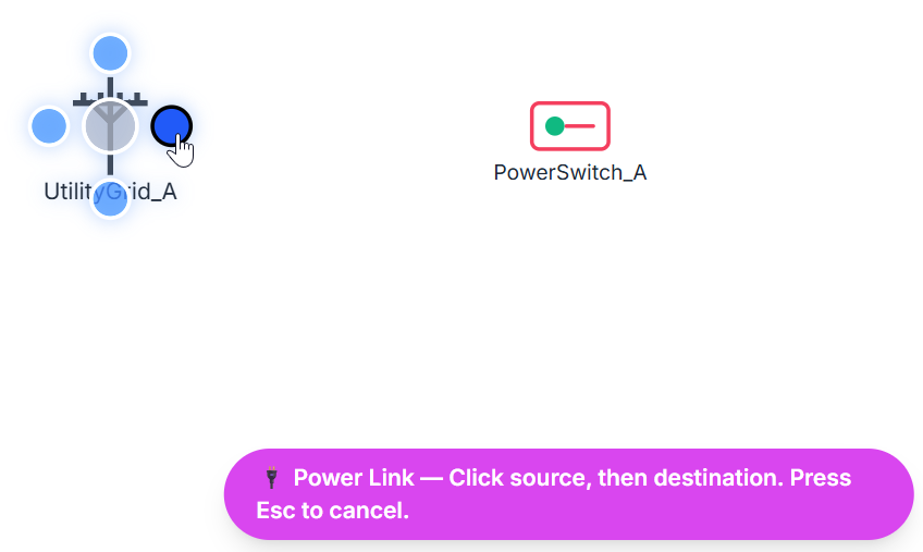
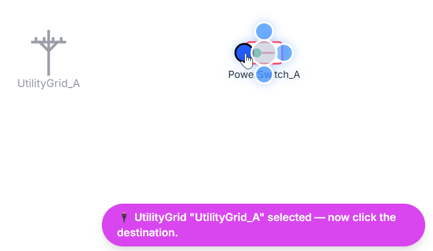
Step 3: The notification bar will update, prompting you to click the destination node. Hover over the destination node (such as a Power Switch, Battery, or Pump) and click to finalize the connection. (Note: You can press Esc at any point during this process to cancel drawing the link).
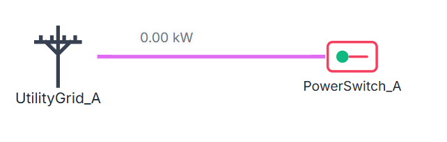
After making the connection, you will see the Power Link connecting the 2 nodes.
Configuration and Properties
Once the connection is established, double-click the link (or right-click it and select Properties) to open the Power Link properties dialog.
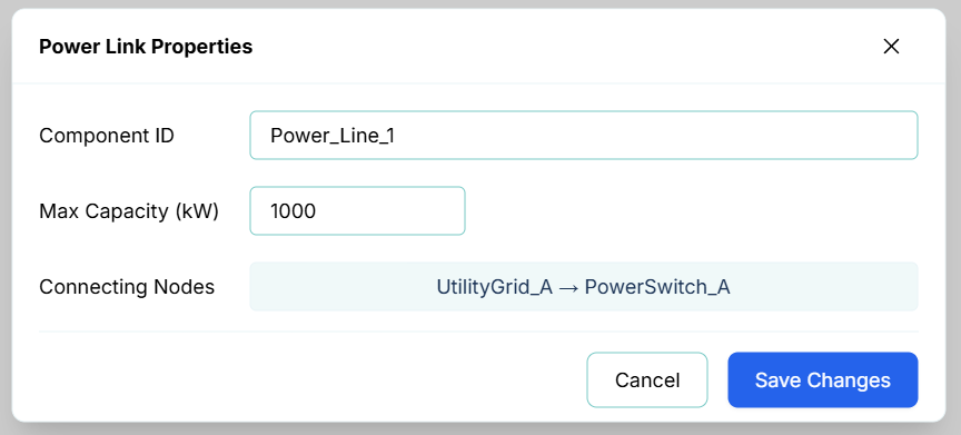
The properties include:
- Component ID: The unique name of the power link (e.g.,
Power_Line_3). - Max Capacity (kW): The maximum active electrical load that the link is physically or contractually rated to carry. The solver utilizes this value to constrain power transmission and distribute active load shares across available parallel network paths.
- Connecting Nodes: Displays the connection direction (Source → Target) defined when the link was drawn.
[!NOTE] Like pipes, Power Links are bidirectional. Even though a source and target are defined during drawing, active power can flow in either direction along the link depending on the real-time electrical balance of the network (e.g., drawing power from the grid to run pumps, or sending power from a generator back to the grid).
Simulation Behavior and Routing
During a simulation run, the R-THYM solver dynamically routes power along active Power Links:
- Capacity Constraints: The solver checks each link's maximum capacity. If multiple paths are available, it distributes active loads without exceeding any link's individual capacity.
- Overload Warnings: If the power flow traversing a link meets or exceeds its configured
Max Capacity, a warning is logged in the simulation warning panel to help you identify overloaded circuits or bottlenecked transmission lines.
Live Telemetry
Single-clicking a Power Link on the canvas during a running simulation displays its live data in the sidebar.

The telemetry panel tracks:
- ID: The unique component identifier.
- Type: The component type (
PowerLink). - Power Flow: The instantaneous active electrical power (kW) currently flowing through the line.
- Capacity Limit: The maximum configured power capacity (kW).
- Dynamic Chart: A rolling chart visualizing power flow (kW) over time. This makes it easy to monitor peak loads, idle periods, or abrupt drops when upstream power switches are opened.