Pump Node
The Pump node is an active mechanical component that adds energy (head) to your hydraulic system. It draws water from an upstream suction node and pushes it downstream at a higher pressure, overcoming elevation changes and friction losses.
[!NOTE] While the Pump is visually represented as a single node in the R-THYM UI to make drawing your network easier, the physics engine dynamically expands it into an upstream junction, a downstream junction, and an internal pump link before solving the hydraulics (as detailed in Appendix A).
UI Workflow and Configuration
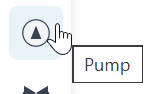
To add a Pump to your model, click its icon in the Component Toolbar and drag it onto the canvas.
Because a pump adds energy in a specific direction, pay attention to the logical direction of your pipes. R-THYM uses logical link-direction mapping to determine the pump's inlet and outlet:
- Inlet (Suction): Any pipe drawn pointing to the Pump (where the Pump is the destination/
tonode) connects to the inlet. - Outlet (Discharge): Any pipe drawn pointing from the Pump (where the Pump is the source/
fromnode) connects to the outlet.
This logical mapping ensures correct flow direction regardless of the visual port/quadrant (Top, Bottom, Left, Right) you use to connect the pipes, allowing for full flexibility in visual layouts.

The primary configuration fields include:
- Component ID and Elevation (ft)
- Pump Type: Choose between
CentrifugalandVertical.[!NOTE] This is purely an asset management and visual metadata classification. The underlying affinity-law hydraulic physics calculations apply identically to both types.
- Pump Motor & Initial Speed:
- Constant Speed: The Initial Speed choice is restricted to exactly 0% (OFF) or 100% (ON).
- Variable Speed: The Initial Speed can be set to any percentage between 0% and 100%, allowing for modulated flow control and continuous PID tracking.
- Start Method & Ramp Time: Choose between
Direct-On-Line(DOL) orSoft Starter. This setting governs the electrical inrush current drawn during the pump's defined "Ramp Time" (the time it takes to spin up from 0% to 100%). - A DOL start is aggressive, applying a 6.0x multiplier to the base power (kW) during startup.
- A Soft Starter is gentler, limiting the inrush multiplier to 3.0x.
[!NOTE] If Variable Speed is selected, the inrush is inherently limited by the VFD to ~1.2x.
- Thresholds: Set limits for Max Starts/Hour and Min Suction (ft) to trigger warnings in the telemetry panel if the pump short-cycles or risks cavitation.
- Rotational Inertia / Transient Settings: Define the physical inertia properties of the pump unit for transient models.
- Rotational Inertia: The combined polar moment of inertia ($WR^2$) of the motor rotor, shaft, and pump impeller, in
lb·ft²(orkg·m²in metric mode). - Rated Speed (RPM): The standard synchronous operational speed of the pump motor (default
1750RPM).
[!IMPORTANT] How Startup/Shutdown Ramping is determined by Simulation Modes:
- EPS (Steady-State) Mode: Bypasses transient settings entirely. Both startup (ON) and shutdown (OFF) speed changes are driven linearly over the defined Ramp Time (sec).
- Transient (MOC) Mode: Uses a hybrid approach: Startup: Governed by the Ramp Time (sec). The speed is ramped up linearly from 0% to 100% tick-by-tick to model a controlled startup (VFD/soft-starter). Shutdown (Power Failure / Trip): Bypasses the linear Ramp Time. The speed decay is calculated dynamically based on the Rotational Inertia (WR^2) and Rated Speed (RPM) as the pump runner naturally slows down against the fluid column. (Setting WR^2 = 0 will cause the pump to halt instantly).
Performance Curves
The bottom of the properties dialog features an interactive performance curve. By adjusting the Design Flow (gpm), Design Head (ft), and Design Eff. (%), R-THYM automatically calculates the theoretical affinity-law curve and updates the graph on the fly. The blue line represents Head vs Flow, while the dashed green line represents Efficiency vs Flow.
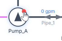
Real-Time Interaction
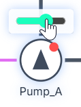
You can interact with a Pump manually while a simulation is actively running. Clicking the small indicator dot on the top right corner of the Pump's node icon on the canvas acts as a manual toggle switch, allowing you to instantly turn the pump ON or OFF in real-time.

Additionally, if you configured the Pump Motor as Variable Speed, an interactive slider will appear above the pump icon during the simulation. You can use your mouse to click and drag this slider to adjust the pump's speed percentage on the fly, and instantly watch the affinity-law effects ripple through the telemetry charts!
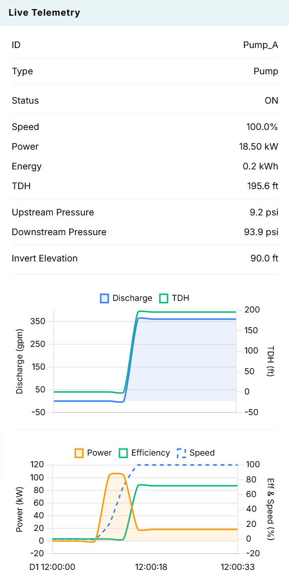
Live Telemetry
Left-clicking a Pump on the canvas reveals its performance data in the right-hand Telemetry Panel.