Hydropneumatic Surge Tank
The Hydropneumatic Surge Tank (often called a "closed surge tank") is a sealed, pressurized vessel containing a trapped gas cushion above the water level. Unlike the open Standpipe, which communicates directly with the atmosphere, the Hydropneumatic Tank uses the compression and expansion of the internal gas volume to absorb transient pressure surges and prevent vacuum formation during low-pressure events.
Functionality in Simulations
The Hydropneumatic Tank is a highly dynamic component, particularly for transient surge analysis:
Steady-State and EPS (Extended Period Simulation)
In EPS, the tank acts as a pressure buffer. It maintains the system's hydraulic grade line (HGL) at the connection point based on the pressure of the trapped gas cushion. It will contribute to the system mass balance as water enters or exits the vessel, causing the gas volume to compress or expand according to the state of the hydraulic network.
MOC (Transient) Simulation
During MOC analysis, this tank is a critical surge mitigation tool. As a pressure wave arrives, the water level within the tank rises, compressing the gas cushion—this work of compression extracts kinetic energy from the pressure wave, significantly dampening the surge. Conversely, if a pressure drop occurs, the compressed gas expands, pushing water back into the pipeline to maintain pressure and prevent column separation (vaporization). The polytropic gas law governs this process, providing a sophisticated, physics-based dampening effect.
UI Workflow and Configuration
To add a Hydropneumatic Tank to your model, click the Hydropneumatic Tank icon from the Surge Control section of the Component Toolbar and drag it onto the canvas.
Double-click on the node or right-click the node and select Properties to configure the vessel's thermodynamic and geometric properties.
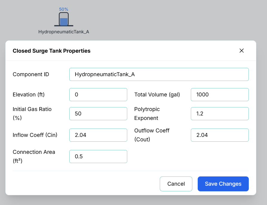
[Placeholder for Properties Image]
The configuration fields include:
- Component ID: The unique identifier for this node (e.g.,
HydropneumaticTank_A). - Elevation (ft): The physical elevation of the bottom of the tank relative to the system datum.
- Total Volume (gal): The total interior capacity of the vessel.
- Initial Gas Ratio (%): The percentage of the total tank volume occupied by the gas cushion at the start of the simulation (Time = 0).
- Polytropic Exponent: The thermodynamic behavior of the gas during compression/expansion. A value of 1.0 represents an isothermal process, while 1.4 represents an adiabatic process. The default of 1.2 is typical for most water-hammer surge control applications.
- Inflow Coeff (Cin) & Outflow Coeff (Cout): Discharge coefficients for the throttling orifice at the tank connection. These allow you to define asymmetric flow resistance, as energy loss may differ when water enters the tank versus when it leaves.
- Connection Area (ft²): The cross-sectional area of the connection orifice. This, combined with the discharge coefficients, determines how rapidly water can exchange between the pipeline and the tank.
Live Telemetry
To view a Hydropneumatic Tank's performance during or after a simulation, simply left-click the node on the canvas. The right-hand Telemetry Panel will populate with its specific data.
The telemetry panel provides insight into the tank's thermodynamic state:
- Instantaneous Metrics: The panel displays the current Pressure at the base of the tank, the current Water Volume, and the current Gas Volume.
- Dynamic Chart: The live chart plots the tank's pressure and volumes over time. During an MOC simulation, this visualization is essential for verifying that the gas cushion is appropriately sized; you should see the gas volume compressing and expanding in response to the transient event, effectively "cushioning" the pressure spikes in the pipeline.