Control Link Basics
A Control Link is a logical feedback path in R-THYM used to automate system operations. Unlike pipes, power lines, or fuel links—which carry physical flows of water, electricity, or fuel—a Control Link carries control signals. It connects a monitoring point (like a Tank, Junction, Outflow Node, or Pipe) to an actuated component (like a Pump, Valve, or Turbine) to control its state dynamically based on real-time telemetry.
R-THYM replaces traditional text-based logical rules (like EPANET's complex RULE blocks) with these visual control connections. This visual mapping makes it easy to set up automatic tank filling, pressure regulating loops, and variable speed pump control.
UI Workflow (Drawing Control Links)
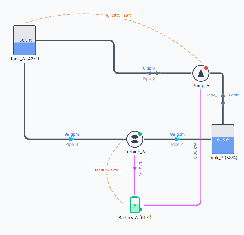
Control Links are represented on the canvas as dashed lines with control icons. Like other links, they must always connect two existing canvas components.
To draw a Control Link, follow these steps:
Step 1: Click the Control Link tool (represented by a dashed line icon) in the Component Toolbar on the left.
Step 2: Look at the instruction bar at the bottom of the screen. It will prompt you to select the starting node (the component to monitor). Hover over the source component (e.g., a Tank or Junction) and click to select it.
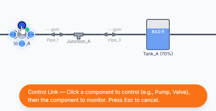
Step 3: The instruction bar will update, prompting you to select the destination node (the component to control). Hover over the target component (e.g., a Pump or Valve) and click to finalize the connection. (Note: You can press Esc at any time to cancel drawing).

Step 4: After you click the destination node, the property dialog appears. For now, accept the default properties and click the Save Changes button to close the properties dialog. At this point, the connection is complete.
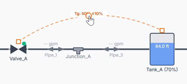
Once connected, the canvas will display a dashed control link between the two components. You can drag the link to a curve that works best for your configuration.
Configuration and Properties
Double-click the Control Link (or right-click it and select Properties) to open its properties dialog.
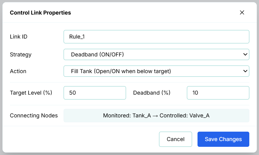
1. General Info
- Link ID: The unique identifier for the control link (e.g.,
Control_Link_1). - Strategy: The control scheme to apply:
- Deadband: Simple rule-based logic (ON/OFF).
- PID (Variable Speed/Position): Modulating variable-frequency drive speed or valve position (0 to 100%).
- Pump Control Valve (PCV): Coordinated pump-to-valve soft-shutdown sequencing.
- Action: The operation behavior defining how the controller reacts relative to the setpoint (e.g., "Fill Tank (Open/ON when below target)" or "Drain Tank (Open/ON when above target)").
2. Controlled Components (Actuators)
A Control Link starts from a controlled component:
- Constant Speed Pumps / Power Switches / Power Generators: Controlled via discrete status (
ON/OFF) using Deadband or threshold settings. - VFD Pumps / Turbines / Modulating Valves: Controlled via a variable speed or position setting (
0to100%) using PID control. - Surge Valves: Controlled via coordinated Pump-to-Valve (PCV) sequencing.
3. Monitored Components and Parameters
A Control Link ends at a monitored component, reading its state dynamically:
- Tanks / Fuel Tanks: Monitors Level (%).
- Batteries: Monitors State of Charge (%).
- Junctions: Monitors Pressure (in user-configured pressure units, e.g., psi or m).
- Inflow / Outflow Nodes: Monitors Flow Rate (in user-configured flow units, e.g., GPM or L/s).
- Utility Grids: Monitors Relative Price (%) (Time-of-Use tariff pattern multipliers).
- Pipes: Cannot be directly monitored. Control links monitor node states; to monitor pipe flows, connect the link to the adjacent Inflow or Outflow node.
4. Control Modes
A. Rule-Based Control (Simple/Deadband)
Simple controls toggle a component's state or setpoint when a threshold is crossed. To prevent the component from rapidly cycling ON and OFF (short-cycling) as the monitored value hovers around the threshold, R-THYM includes a Deadband buffer.
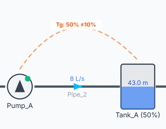
- Target Value: The threshold value for the monitored parameter (e.g.,
50% Level). - Deadband Buffer: A buffer region centered around the target value. For example, if a Pump has a Tank Fill action targeting a level of 50% with a Deadband of 10%:
- The pump turns ON when the level drops below 45% ($50 - 10/2$).
- The pump remains ON and turns OFF only when the level rises above 55% ($50 + 10/2$).
B. Continuous PID Control (Proportional-Integral-Derivative)
For variable-frequency drive (VFD) pumps, modulating control valves, or adjustable turbine gates, R-THYM features a discrete-time PID controller. The orchestration engine continuously calculates the difference (error) between the monitored value and your setpoint, computing P, I, and D corrections to seek a steady state.
- Target Setpoint: The desired value for the monitored variable (e.g.,
50% or a specific pressure). - Kp (Prop.): Adjusts output proportionally to the current error.
- Ki (Integral): Adjusts output based on accumulated past error, eliminating steady-state offset.
- Kd (Deriv.): Adjusts output based on the rate of change of the error, dampening overshoot.
- Timestep Scaling: The controller's calculations dynamically scale using the simulation's actual elapsed time per tick (timestep
dt). This ensures stable feedback control and prevents rapid, unphysical oscillations regardless of simulation speed.
General Telemetry Info
Connecting Nodes: Displays the connection roles and route (e.g., Monitored: Tank_A → Controlled: Valve_A) at the very bottom of the dialog. This clarifies the logical signal path, indicating which component acts as the sensor/telemetry source and which component is operated.
Simulation and Transient Behavior
During a simulation run, the R-THYM engine evaluates all active Control Links at each time step:
- Rule Evaluation: For Rule-based links, the engine evaluates the deadband state logic and updates the physical status of pumps, valves, or turbines.
- Feedback Loops: For PID links, the controller updates its internal error history and outputs a modulated target setting percentage (e.g., varying pump speed factor from 0.0 to 1.0, or modulating a valve opening).
- Slew Rate & Ramping Limits: When a Control Link commands a change in state or setpoint, the target component honors its configured physical ramping limits. For example, a valve commanded to close by a control link will close gradually over its configured closure curve rather than shutting instantly, allowing high-fidelity transient water hammer waves to be simulated accurately.