Air Valve
The Air Valve (commonly referred to as an Air Release and Vacuum Breaker Valve) is a mechanical protection device positioned at pipeline high points. Unlike the open Standpipe or the pressurized Hydropneumatic Surge Tank, the Air Valve remains completely closed during positive pressure conditions and activates dynamically during low-pressure transient events to admit atmospheric air, cushioning pressure drops and preventing dangerous pipeline collapse (deep vacuum).
Functionality in Simulations
The Air Valve acts as a critical dynamic boundary during transient analysis:
Steady-State and EPS (Extended Period Simulation)
Under steady-state conditions, the Air Valve operates as a standard pipeline junction. It does not alter active system demand or boundary heads, provided the system maintains positive pressures above the local elevation.
MOC (Transient) Simulation
During transient surge events (such as pump shut-offs or rapid valve closures), the Air Valve is key to vacuum prevention:
- Air Admission (Vacuum Prevention): If the local hydraulic grade line (HGL) falls below the physical elevation of the valve, a sub-atmospheric pressure condition arises. The valve immediately opens to admit atmospheric air. The rate of air entry is governed by the Admission Diameter and the Inflow Loss Coefficient. This admitted air forms an isothermal gas pocket at the high point, clamping the local head near the physical elevation of the valve and preventing the pressure from dropping to the destructive vapor pressure floor (
-14.30 psi). - Air Release (Cushioned Recompression): As the low-pressure wave reflects and fluid columns return, pressure increases, and the admitted air is expelled. The release rate is governed by the smaller Release Diameter and Outflow Loss Coefficient. This asymmetrical throttling restricts air release, acting as a pneumatic shock absorber that cushions the deceleration of the returning water columns and dampens the resulting high-pressure spike.
- Pocket Collapse: Once all trapped air is fully vented, the valve closes, and the solver returns to standard liquid-only MOC calculations.
UI Workflow and Configuration
To add an Air Valve to your model, click the Air Valve icon from the Surge Control section of the Component Toolbar and drag it onto the canvas.
Double-click on the node or right-click the node and select Properties to configure the valve's thermodynamic and orifice properties.
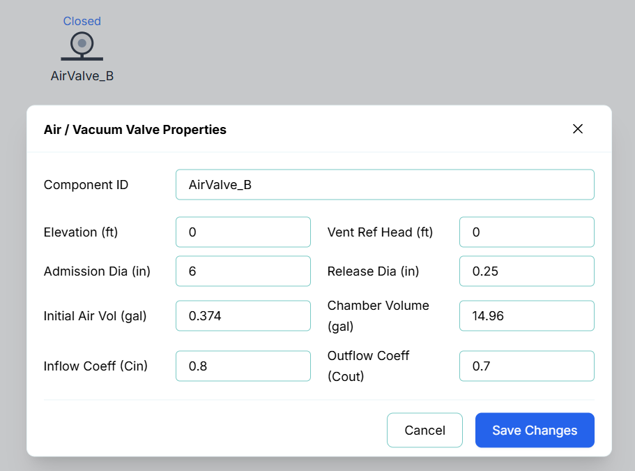
The configuration fields include:
- Component ID: The unique identifier for this node (e.g.,
AirValve_A). - Elevation (ft): The physical elevation of the valve inlet relative to the system datum.
- Admission Diameter (in): The orifice diameter for air entering the pipeline during vacuum breaker conditions.
- Release Diameter (in): The orifice diameter for venting air from the pipeline. This is typically much smaller than the admission diameter to ensure cushioned recompression.
- Admission Coeff (Loss Coeff In): The inflow loss/discharge coefficient for air entering the valve (typically
0.8). - Release Coeff (Loss Coeff Out): The outflow loss/discharge coefficient for air leaving the valve (typically
0.7). - Initial Gas Volume (gal): The volume of air present in the valve at the start of the simulation (Time = 0). Normally set to
0.0. - Chamber Volume (gal): The maximum physical volume of the air valve chamber (typically
15.0 gal). - Vent Ref Head: The gauge head offset above the node elevation for riser/offset vent seat configurations. Normally set to 0.0.
Proper Component Placement
For effective transient mitigation and air management, Air Valves must be strategically positioned at vulnerable points along the pipeline. Proper placement guidelines include:
- Local High Points (Grade Breaks): Always place an Air Valve at local peaks where the pipeline slope changes from ascending to descending. These points are highly susceptible to column separation and vacuum formation during low-pressure transients.
- Long, Uniform Slopes: On long, continuous uphill or downhill pipe runs, place air valves at regular intervals (typically every 1,500 to 3,000 ft or 500 to 1,000 m) to prevent pockets of air from accumulating and causing air binding.
- Downstream of Pumps and Check Valves: Position an Air Valve immediately downstream of check valves and pump stations. During a sudden pump trip, the rapid deceleration of flow can pull a severe vacuum right behind the check valve; the Air Valve immediately admits air to cushion the pipeline.
- Upstream of Control Valves and Flow Meters: Place valves upstream of pressure-reducing valves (PRVs) or flow control valves. Pocketed air arriving at a control valve can cause severe control oscillations, high-velocity throttling, and instrumentation errors.
- Significant Decreases in Slope: Even if the slope doesn't turn downward, a sharp decrease in upward slope (a "relative high point") reduces flow velocity and creates an area where pocketed air will naturally settle.
Live Telemetry
To view an Air Valve's performance during or after a simulation, click the node on the canvas. The right-hand Telemetry Panel will populate with its specific real-time data.
The telemetry panel provides insight into the valve's physical and pneumatic behavior:
- Instantaneous Metrics: Displays the current Pressure at the valve, the current Air Pocket Volume, the instantaneous Air Loss Rate (Venting), and the Cumulative Air Loss (total air volume vented).
- Venting Status Indication: The valve turns Green on the canvas when active (an air pocket is present) and reverts to Gray once collapsed. Additionally, the text label directly below the node on the canvas dynamically updates to display the active volume (e.g. Air: 4.2 gal) or Closed.
- Dynamic Chart: The live chart plots both the pressure and air volume over time. During an MOC simulation, you can track the growth of the air pocket during the initial pressure drop, followed by its gradual, cushioned decline as the air is expelled and the columns re-integrate.