Inflow Node
The Inflow Node is used to inject a defined flow rate of water into your network at a specific location.
If you are familiar with EPANET terminology, an Inflow Node is equivalent to a standard Junction node configured with a negative base demand. However, R-THYM breaks this out into a dedicated component to make it visually distinct and easier to configure.
Functionality
Unlike a Pressure Boundary (which provides water at a constant pressure regardless of flow), an Inflow Node provides water at a constant flow rate regardless of the resulting system pressure.
Common use cases for an Inflow Node include: - Modeling a feed from a groundwater well operating at a fixed flow rate. - Simulating a booster station discharging into your network from an external, unmodeled source. - Representing steady industrial return flows into a municipal system.
UI Workflow and Configuration
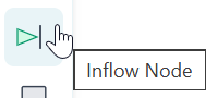
To add an Inflow Node to your model, click its icon (which resembles a triangle pointing into a vertical line) in the Component Toolbar and drag it onto the canvas to place it.
Right-click the node and select Properties to open the configuration dialog.
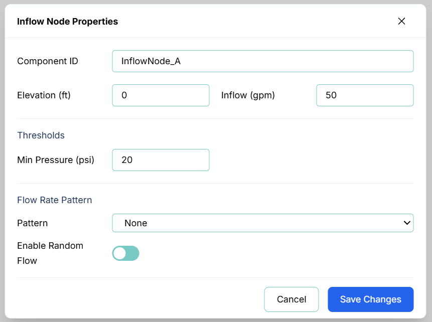
The primary configuration fields include:
- Component ID: The unique identifier for this node (e.g.,
InflowNode_A). - Elevation: The physical elevation of the node above sea level (or your chosen datum), measured in length units (e.g., feet or meters). This is critical for accurate pressure calculations.
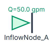
- Inflow: The baseline volume of water injected into the system per minute (e.g., gpm or L/s).
- Thresholds (Min Pressure): You can set a minimum pressure threshold. If the pressure drops below this limit during a simulation, a warning will be triggered in the Telemetry Panel.
Flow Rate Patterns
Just like Pressure Boundaries, you can assign a time-varying pattern to an Inflow Node to simulate fluctuations over time (such as peak daytime well pumping versus nighttime resting).
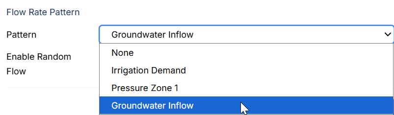
Selecting a pattern (like Groundwater Inflow) applies a multiplier to the base Inflow value over the course of the simulation.
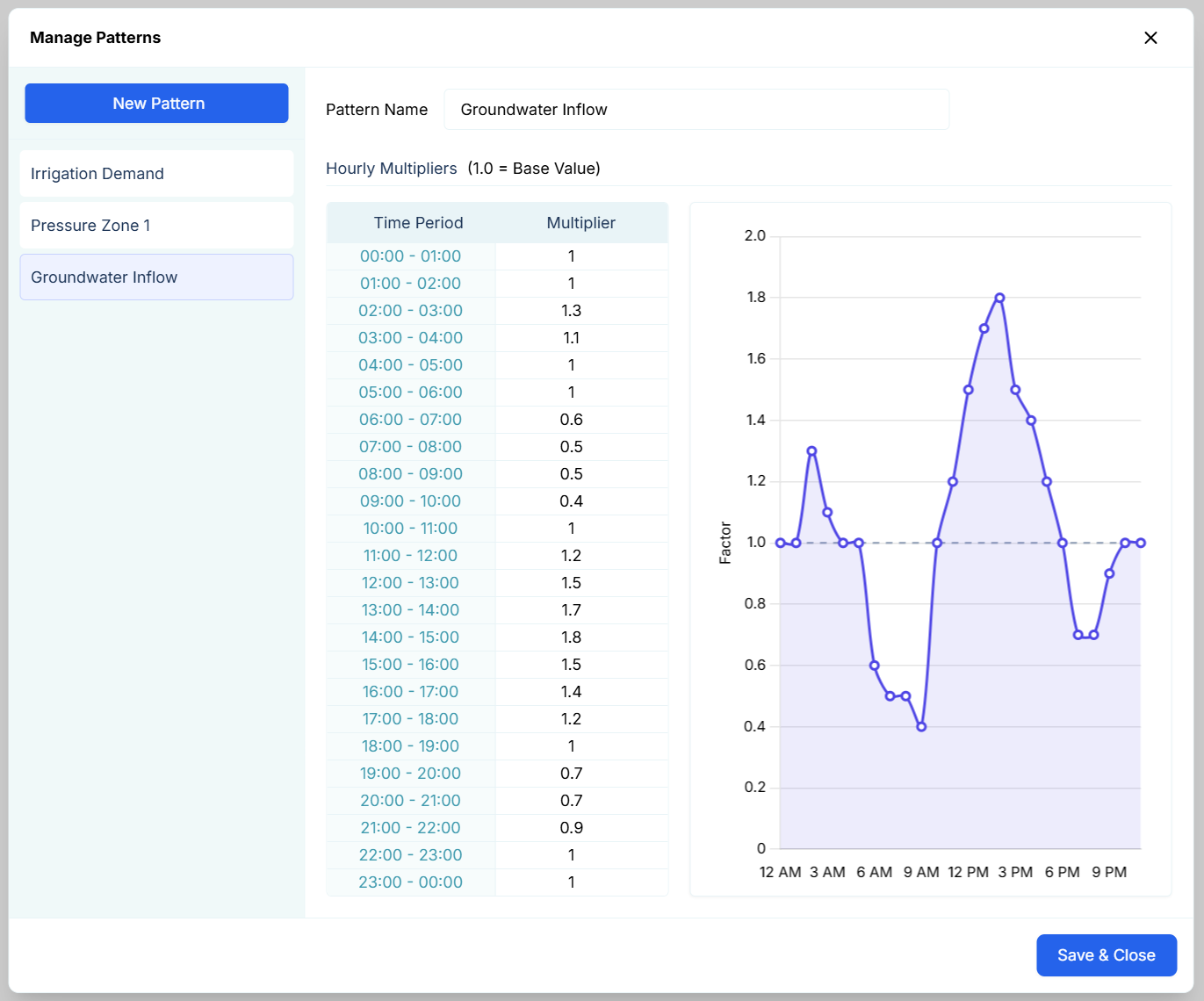
For instance, the Groundwater Inflow pattern shown above might represent a well pump that runs at 100% capacity (a multiplier of 1.0) during off-peak nighttime hours, and completely shuts off (a multiplier of 0.0) during peak daytime hours to save energy. By assigning this pattern, your Inflow Node will automatically adhere to this daily schedule without any manual intervention.
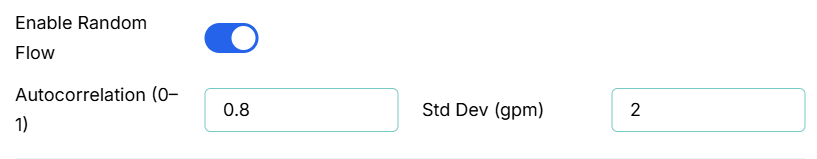
Random Flow (Stochastic Modeling)
For advanced modeling, you can enable the Random Flow feature. This injects stochastic (randomized) noise into the inflow rate to simulate realistic, unpredictable variations in real-world systems.